DIY projects / 10 July 2024
Building an active pedal: an introduction to the DIY project

In July 2024, I present my first completed DIY active pedal, built from a community project I discovered through Ludovic. My aim was simple: change position, travel and resistance from the seat without dismantling springs or elastomers. The video covers the build, adjustments to my printed parts and getting started with the SimHub plugin that controls the assembly.
A community project for discovering active pedals
The project is based on GitHub documentation, a component list and discussions in the FFB Pedal community. Seeing a completed example working made me want to build one. I am therefore not developing the electronics myself: I use a shared foundation and adapt the construction to what I want on my cockpit.
At the time, I discuss around €400–500 for one pedal, with a lower cost per unit when building two. Those are approximate figures for my 3D-printed project, rather than the price of an assembled product. The printer, tools and working time are also part of the experience.
How my version works
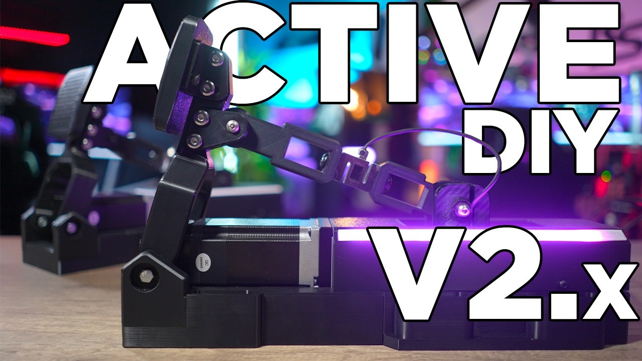
The pedal face transmits force to a lever mounted on bearings. A 200 kg load cell measures pressure and the electronics command the motor, which moves the carriage along its rail and returns the pedal. Resistance and movement therefore no longer depend solely on a spring or stack of elastomers.
I added a compartment for the Power PCB and its capacitor to house the electronics neatly. My goal is an assembly I can mount to the cockpit and then adjust mainly through software. That flexibility is what attracts me most after repeatedly moving between my seat and the mechanical adjustments on previous pedals.
Preparing the electronics and cables
The work starts with the project files and bill of materials. PCBs are ordered from a circuit-board manufacturer. My order comes in batches of five, leaving spare boards to share with other builders.
The board takes an ESP32, an ADS module and a voltage regulator among other components. Connectors and components require many solder joints. This is one of the longest stages: I need patience and careful connections before proceeding.
I also prepare JST cables linking the board to the sensor and motor. The video presents this work and the parts used, while the project documentation remains the reference for schematics and versions. This summary does not replace the wiring diagram corresponding to the selected boards.
3D printing and mechanical corrections
I went through several prototypes. I revised holes, distances between parts and countersunk screw recesses. I also designed a board support beneath the pedal and a small closed compartment for the power electronics.
My old printer had under-extrusion problems, so I replaced it with a Bambu Lab P1P to obtain more consistent parts. On this build, some bases use 25% infill, while parts directly receiving force, including the face and fork, use 100%. Those figures describe this specific construction.
I use inserts where I want clean threaded fixings and a thicker face to accommodate them. Friction between the fork and base also led me to raise part of the design slightly. Rail assembly then requires patience to reach the nuts and secure it from the sides and underneath.
Sleeved fasteners and bearings form the lever joints. Once the carriage-to-pedal connection is assembled, the complete mechanism takes shape. I do not directly share this personal design, which is heavily inspired by an existing model; community resources provide the starting point for a build.
Firmware, calibration and initial settings
The ESP32 is flashed using the webflasher specified by the project. The firmware version must match the SimHub plugin version. Initial startup performs calibration and produces more noise than my normal driving movements.
In the plugin, I choose starting and ending points to position the pedal and define travel. I can shorten braking travel or move the whole range without changing the mechanism. Curves, preload and control parameters then alter resistance and return behaviour.
Here I prefer PID control, with around 30 kg of force, to an excessively lively response. Changes are sent to the pedal through the configuration command. Some curve behaviour does not yet match my expectations exactly, and I have sent that feedback to the developers.
ABS and driving feel
ABS is one of the effects that interests me most. The motor acts on pedal movement, giving a different sensation from a simple added vibration motor. I adjust waveform, frequency and intensity, then test the effect directly in the software.
Profiles let me recall different travel and force settings for different cars. I want a relatively soft initial pedal that becomes firmer towards the end. This adjustability helped me find my reference points quickly.
The rail has noticeable resistance when unpowered, and some mechanical character remains underfoot. My enthusiasm concerns what I built and used; the Simucube comparisons discussed at the time are not a direct head-to-head test. This first version chiefly opens the way for further hardware and software improvements.
Join the discussion on YouTube